As an Amazon associate we earn from qualifying purchases. Thanks for your support!                               
×

Best Blu-ray Movie Deals


Best Blu-ray Movie Deals, See All the Deals »
Top deals | New deals  
 All countries United States United Kingdom Canada Germany France Spain Italy Australia Netherlands Japan Mexico
Superman I-IV 5-Film Collection 4K (Blu-ray)
$74.99
 
Weapons 4K (Blu-ray)
$27.95
1 day ago
One Flew Over the Cuckoo's Nest 4K (Blu-ray)
$29.99
1 day ago
The Dark Knight Trilogy 4K (Blu-ray)
$28.99
1 day ago
The Mask 4K (Blu-ray)
$45.00
 
The Conjuring: Last Rites 4K (Blu-ray)
$27.95
3 hrs ago
A Better Tomorrow Trilogy 4K (Blu-ray)
$82.99
 
Wallace & Gromit: The Complete Cracking Collection 4K (Blu-ray)
$13.99
16 hrs ago
Batman 4-Film Collection 4K (Blu-ray)
$32.99
1 day ago
I Love Lucy: The Complete Series (Blu-ray)
$44.99
1 day ago
Creepshow: Complete Series - Seasons 1-4 (Blu-ray)
$84.99
1 day ago
Nobody 2 4K (Blu-ray)
$27.95
 
What's your next favorite movie?
Join our movie community to find out


Image from: Life of Pi (2012)

Go Back   Blu-ray Forum > Home Theater > Home Theater Galleries
Register FAQ Community Calendar Today's Posts Search


Reply
 
Thread Tools Display Modes
Old 11-23-2013, 12:19 PM   #1
mtbdudexdad mtbdudexdad is offline
Active Member
 
mtbdudexdad's Avatar
 
Nov 2013
Default My 6+ year HT journey: 11.3 Audio, 130" scope screen, other - including basement

This has been a 6+ year project/journey for me, first couple of years I only worked on it Dec thru March, and even then just weekends, sometimes just 3-4 hours/weekend due to young kids and busy schedule/etc.
Overall I did everything except drywall, love DIY, learned so much.

The original 4 year Timeline:
(this was never planned as a 4 year project, initial thought was two years, but life got busy)
-Dec 2004 thru March 2005: Plan & design, changed the stairs going into the basement from a "L" layout to a "U" layout, frame all the walls, tighten log wall rod spring system
-Dec 2005 thru March 2006; Bath copper plumbing, re-do shower drain (add P-trap)/partial HVAC runs (I ran both hot and cold air supply for each room reciric)
-Dec 2006 thru March 2007; Finish HVAC, foil sealed ALL seams on HVAC runs, built home theatre seat riser section, re-tighten log wall rod spring system, sealed bond areas
-Nov 2007; I installed new H20 softener system and a RO system (gave up on my 5 year $5k salt free Whole Home H20 EcoSmarte system)
-Dec 2007 thru Feb 2008; Plan and did all Electrical (almost 2,000 feet of 14/2, 14/3, and 12/3 romex), ran 500 feet of 14/4 speaker wire for Home Cinema room + Zone 2 and Zone 3 speakers in rec room and Craft room, cables/Cat5 wire for Frt Proj/subwoofer ran, decide to add sink to rec room, cut concete floor and plumb for drain and supply, contracted drywall was started on 12/27/07 and they just finished Friday 1/18/08.
-Jan 2008 thru Aug 2008; IB 4 x 15" line array subwoofer

Functional and used for 2 years, then got desire to improve acoustics/etc

Added timeline items:
-Dec 2010 thru June 2011 Acoustic treatments
-Dec 2012 thru March 2013 7.1 to 11.3 Audio upgrade
-Dec 2012 thru April 2013 added 2 subwoofers for flat freq response

Current "HT journey" status:
HT Layout:


HT pictures
Screen shot:


Rear shot:


Basement layout:


Here is our custom log home, we built our loghome and moved in May-2002, here it is, front and back showing walkout view:
.

Gear list:
Front Proj: Sony VPL-VW60 + a-lens UH380 on slide, with Darbee Darblet video processor
A/V: Denon AVR-4520CI + Emotiva XPA-3 amp
Screen: 130" DIY 2.35:1 curved screen
11.3 speakers: Paradigm Monitor 9's for front, CC-390 center, 4 ADP-390 for rear and back surround, Monitor bookshelf for wides/fronts.
2000 Onkyo 787 driving zone 2/3
subwoofer: 4 x 15" IB array on Sub1, plus 18" and 15" Stereo Integrity cubes on Sub2
speaker wire: 500 feet of 14ga/4c, all runs equal length.

Last edited by mtbdudexdad; 04-01-2016 at 11:12 AM. Reason: added current gear list Nov-2013
  Reply With Quote
Old 11-23-2013, 12:20 PM   #2
mtbdudexdad mtbdudexdad is offline
Active Member
 
mtbdudexdad's Avatar
 
Nov 2013
Default

reserved for Dec-2004 thru Feb-2008 basic construction cliff notes
Year1:
-Dec 2004 thru March 2005: Plan & design, changed the stairs going into the basement from a "L" layout to a "U" layout, frame all the walls, tighten log wall rod spring system

Before: Big/open 1,300 sq feet basement
.

Have a plan, transfer that plan to the concrete via snapping chalk lines, confirm plan to reality.
We modified the plans a few times based on chalk lines and just talking things thru.
a) initially the HT room went E-W instead of N-S like it is (our home faces East), but because it was next to the Utility room I was concerned with HVAC equipment noise, so changed it as shown. That also made me change the downstairs from a "L" to a "U", which meant the very first thing I did before putting up walls was actually tear down walls and built stairs. Also, added the 45deg corner on the craft room for better walk flow into the bathroom/bedroom. That also will make it easier for bedroom furniture movement, plus when the drywallers put the 12 foot sheets in the bedroom that allowed for them.

Measure twice, cut one. Even then occasional FuPau happenes. No problem, almost every piece of wood was used, very little scrap.
Plus, my kids were able to "play builder" with all the small wood pieces I kept and entertain themselfs while I worked.

Changing stairs from "L" to "U":
Before, "L": After, "U"
.

I built all my walls "in place", i.e., put the top and bottom plates on first then the individual studs.
Others build a wall on its side and lift into place.
I used wood studs instead of the newer steel studs, just felt more comfortable with them, my friend used the steel studs and loved them, no warping.
I used std 2 x 4 wall construction for most of the walls, the Home Theatre inside 2 walls I used 2 x 6 top/bottom plated and then staggered 2 x 4's for more sound isolation. The outside walls are Michigan Superior Concrete walls.
More on that in year 4.
.

That is Year1 very briefly, cut lots of wood, love the Paslode framing gun, nice to have my dad over at times for that 2nd hand, when nobody was around Iearned other techniques (temp nail, clamps, etc).
I loved this phase, OJT and very visual to see progress as studs went up.
Nice to have a simple $40 laser also for long straight run check.

Brief re-cap of Year2 (Dec2005 - Mar2006)
Year2:
-Dec 2005 thru March 2006; Bath copper plumbing, re-do shower drain (add P-trap)/partial HVAC runs (I ran both hot and cold air supply for each room reciric)

I've never really sweated copper pipes before, etc. So, did a lot of reading, planning, made a 3D sketch (by hand) of the new Hot/cold supply routing. Made a BOM, added 10%, did a Home Depot run, ended up using about 87 feet of copper piping, at least 70+ fittings (90 deg, 45 deg, etc). I got pretty good a sweating the copper. Use H20 air hammers everywhere so no noise issue, maybe a little overkill but only $12/each.

My DIY plumbers Secret:
Pressurize the system with air and test for leaks before sweating final hot/cold joints.
I used a simple $4 1/2" faucet w/compression joints that has a schrader valve on it, would attach that to the pipe supply, pump it to 40-50 psi, take soapy water, brush it on the joints I sweated, and hopefully no bubbles (no leaks).
Of the 70+ joints I sweated found 1 leak, quickly re-sweated it. This took 15 extra minutes but gave me, a DIY plumber a sense of confidence.
This picture shows the temp faucet (has compression fittings) at the old/new pipe junction.


Future toliet supply:


Future sink supply:


Future shower supply:


In a log home difficult to rech vent pipes, so air intake vent are used (and approved by code in Livingston county, Mich). However, I was concered that my builder did not take that into account for the shower drain, venting, so I realized I needed to "cut the concrete" to vent that drain. In doing so, I also found out he (the plumber) did not install a p-trap beneath the shower drain, w/o that septic gas would have seeped into the shower, stinky. Therefore I fixed that and added piping for air intake.
Before showing shower drain wrongly done by original plumber w/o p-trap.


I added p-trap and routed for air vent.
.

Year3 (Dec2006 - Mar 2007) re-cap next post

Last edited by mtbdudexdad; 11-23-2013 at 12:36 PM.
  Reply With Quote
Old 11-23-2013, 12:20 PM   #3
mtbdudexdad mtbdudexdad is offline
Active Member
 
mtbdudexdad's Avatar
 
Nov 2013
Default

Year3 brief re-cap Dec 2006 thru March 2007(time goes by so quickly)
-HVAC supply/return runs each room
-foil sealed ALL seams on HVAC runs, including existing HVAC,
-built home theatre seat riser section (gave HT room some image to theatre now)
-sealed bond areas around total perimeter of home (8-10 cans of foam sealant)
-re-tighten log wall rod spring system
This picture shows the current log home tightenting system, effective from 2003 models, mine is similiar but the spring is on the bottom (in basement) and requires tightening 2-3 times over a 5 year period while the logs settle.
(Heritage Log Home system)


The close loop GeoThermal system was properly sized for the additional basement load when I built the home.
As a matter of fact, we even had in floor heating in our original home plan, but took it out during building because we went over budget.

I put traditional supply vents on the bottom and return vents on the top in each room for air circulation.
Yes, I do realize that looking at HVAC vents is kinda boring for an audio topic, but you never know, others are in their process and this might help them imagine some method for their project. I do look at others in process stuff to gather my ideas.
I always balanced same supply/return for each room, and further put "closeable" grilles on each so I could balance each room.

Decision time:
At one time I did consider putting a zoned system in, would have costed me $2k for all the duct dampers/bypass/etc, but our house is pretty balanced from the original contractor, even with big open loft in summer if it's 70 on 1st floor only 73 in 2nd floor, still liveable and decent, so I decided to save the $2k. My friend did not have his HVAC unit sized to include his basement, so when he did his adding the zone made it possible for him to keep the same HVAC unit.

Just a few picts:
Return vents in 4th bedroom


Bathroom view of craft room return vent


Bathroom room supply duct, view from craft room:


Home theater riser, egg crate similiar to other risers, built in-place so put lower sheet of drywall in 1st:
(there is a 1/4" gap to the drywall so no vibration transmission, I put soft DAP there, it will be covered by carpet)
.

-Plan and did all Electrical (almost 2,000 feet of 14/2, 14/3, and 12/3 romex),
-Electrical planning and layout:
Tapped into 3 existing circuits and added 10 new circuits:


Overview schematic of wiring:


Home runs at main panel waiting to be connected:
After working so hard on the wiring phase, I understand the term "home run", felt for each circuit to run that final length.
I have (2) 200 Amp supply panels, my home is 100% electric, no gas/oil.
One panel is dedicated to the GeoThermal unit and the H20, while this one is the main home supply panel.


Box on top is fed by 60A double breaker in the main 200A box, it feeds the majority of the basement (non HT) stuff.


There is a 2nd box (no pict) below that box feeds some basement circuits and the HT lighting circuits, I also used 2 slots in the 200A main to feed ground isolated circuits for the IB sub seperately and the other A/V gear.

I did not have enough space next to the 200A box for a 100A box, so instead used 2 smaller boxes.

I started out by totally understanding my current 200A box circuit layout.
Traced/confired each circuit. Since I built my home I wish I had my electrician stuff for this, did not ask for it back in 2002.


Listed my new basement/HT circuit needs


Refer to code book (from Dec-2007):
.

Did circuit load analysis to confirm within existing 200A box capacity


ran 500 feet of 14/4 speaker wire for Home Cinema room + Zone 2 and Zone 3 speakers in rec room and Craft room.
Empty spool of 500 ft 14/4 wire in A/V closet after many long nights.
The A/V closet had "back doors" for easy access from the rec room side, no need for any sliding system.

Last edited by mtbdudexdad; 11-23-2013 at 01:13 PM.
  Reply With Quote
Old 11-23-2013, 12:21 PM   #4
mtbdudexdad mtbdudexdad is offline
Active Member
 
mtbdudexdad's Avatar
 
Nov 2013
Default

reserved for IB sub cliff notes
This is my first DIY speaker project.
At the IB Cult forum I was able to learn/build/create a neat looking (4) x 15" line array IB subwoofer, with fantastic sound capabilities. 12/21/07 was my 1st build thread post and was a 1 year journey.

I've named this IB subwoofer "Usul", because I had to cut thru rock (concrete foundation wall) to make this project a reality, you'll see that below.

I went from thinking about a Dayton HPSA1000-R 1000W Rackmount Subwoofer Amplifier to power 4 Dayton IB385-8 15" IB Subwoofers; to eventually (4) AE IB15's driving them with the Behringer EP2500 Europower Power Amp, EQ Behringer FBQ2496 Feedback Destroyer.

My total investment is around $1.3k, speakers, amp, EQ, mounting boards, hardware, speaker grille cloth, etc.

Mechancial:
-I built a 4 x 15" array, it's backwave vents directly into the utility room. That is closed off from the rec room via sealed door. I did more isolation via 1" styrofoam/sealant at HVAC duct locations.
I was concerned about the bass booming the HVAC ducts, since my GeoThermal system is in the utility room and it has sheetmetal HVAC supply/return main lines entering/exiting the room. If there was a duct boom I thought to add some damping method to that problem area. (like a mastic patch to stiffin the duct/etc). That was not needed.
-The array is vertical and on the RH side of my DIY 130" screen. That is due to practical layout.
-My basement is a engineered foundation, the walls are concrete on outside 3-4 " thick, with 2" foam insuation, there are load bearing concretre "studs" 9" deep on 24" centers, these have 3/4" wood attached to them for hanging drywall. My line array baffle plate was mounted to the foundation wall via threaded rod and lag screws. Very solid/rigid, basically 0 in plane motion unlike other line arrays that mount to stud walls.


Planning/cutting the concrete foundation was the 1st major hurdle.

I consulted with Michigan Superior walls and got the information needed to "cut a interior window" in my foundation wall, this was great news, IB array can directly be mounted and the backwave simply radiate into the utility room. Prior I had "wrong/less desirable" ideas.


Since I have a log home, my roof loads are on the front / back walls transferred there via the ceiling/roof beams, not the side (gable) walls.
The foundation wall I'm "cutting a interior window" is on the gable side of my home, just makes things a little easier.

This just shows a lot of thought/planning/design detail has to go into a project before actual construction starts, and during as you run into "unknowns".
Prep area with plastic sheeting to keep concrete dust in control (gosh there was lots of dust, way more than I figured)


16" x 66" IB sub "window", the concrete stud was a royal PIA to remove, my speaker wires were ran thru 3/4" pre-drilled holes on center, so I had to induce cracks there and remove the concrete stud w/o damaging the wires, and remove the rebar rod, 100% success.
.

Sub-woofer porn shot 4 AE IB15's, now the fun began.


Started with detailed baseline of actual existing construction situation on grid/graph paper:


Made a real size paper template, mounted it to see/confirm/modify design.
>>Full size is much better than some scale drwg, gives a real feel for the mounting/other details.
HT side (line array is mounted on this side). I had to cut 1 3/4" slot for the MDF/OSB plate to fit in for mounting on the RH side.
Before drywall, 4 years ago during the framing phase of the basement/HT, I put a 2 x 4 along the concrete joist via construction adhesive and nails, that is my RH side attach point.
That also means the total thickness from inside the HT room will be that 1 1/2" + 1 1/2" for the OSB/MDF sandwich, so 3" step into the HT room side.
View from utility room side, green shows 2 x 4 pressure treated wood I plan on using to "clamp" the OSB/MDF sandwich tightely against the concrete walls/studs AND control in plane stiffness/flex
.


Cut both MDF and OSB board to 25 1/4 width, glue and lot's of weight. Spread glue.
.

Weights and constant wiping of the glue that got squeezed out from the sandwich. I found a flat portion of my garage bonus floor, so sandwich OSB/MDF should be flat. Used some scrap 2 x 4 blocking to hold the slippery sandwich together.


put two scrap 2 x 4's underneath to support the cutout holes - after I did NOT do it for the 1st one....small lesson learned.
Nice day to do this outside, lot's of DUST!
1 hole done, 1 in progress; then all 4 done, I ended up with 3 1/4 inch of board between drivers:
.

"Cheese" smile from my son, baffle plate mounted, seeing fit situation, everything looks like it should. Now temp mounted one of the AE IB15's.
.

Ok;
I know this is corny, but while I was working downstairs (way back in May 2008) I got this strange urge to name my IB sub-woofer, and this name instantly popped into my head and stuck, so without further delay I'd like to introduce...

"Usul-the rock of IB subwoofers"
.

IB Baffle secured to foundation wall via (11) 1/2-13 threaded rod as primary mounting "clamp" and additional (10) 3/8" lag bolts into 2 x 4's on both sides as secondary securing.
Plus, I used (10) 1/4 x 2 1/4 concrete screws to secure the 3/4" wood furing strip that came attached to the concrete studs that hold the 2 x 4's , for added secure/rattle proofing.
Usul is ROCK solid!
.

The outer (2) threaded rods actually provide the holding force, while the middle one is a support and adjusted to keep the baffle plate flat for speaker mtg (I'm still using 1/2" foam for 100% sure seal).
On the baffle side I use a self-locking hex nut and big washer to distribute load, the other 3 interface used big washer/lock washer/hex nut.
I counter-sunk the front nuts so veneer is still possible.

Drill/glue and install (12) 3/8 dia "super" magnets:
(polarity marked RED and installed seeing that to make sure same, what a pain to seperate each individual magnetic and then mark-it, but had to be done)


Measure/cut laminate, Contact cement brushed onto baffle plate, be careful drips/sags:
.

Contact cement brushed onto laminate, use rotating fan to speed up drying of contact cement on laminate to match baffle plate
.

router AND drywall cutter for "tight" spots, that drywall cutter worked quite well, was able to use it no problem.
.

Foam sealing gasket in place for each driver, backside of lowest driver:
.

View from utility room, head shot:
.

Last edited by mtbdudexdad; 11-23-2013 at 04:31 PM.
  Reply With Quote
Old 11-23-2013, 12:21 PM   #5
mtbdudexdad mtbdudexdad is offline
Active Member
 
mtbdudexdad's Avatar
 
Nov 2013
Default

reserved for Acoustic treatments cliff notes
Get educated! A great 1st book is "Master Handbook of Acoustics" by F. Alton Everest, a perfect follow-up book is "Sound Reproduction: The Acoustics and Psychoacoustics of Loudspeakers and Rooms" by Floyd Toole.
Knowing that for “best” audio/sound in a listening room, these parameters are tackled in prioritized order:
1. Speaker location, 2. Listener position, 3. Acoustic treatments, 4. Electronic correction.
Understand the small room acoustic model you will follow.
Looking at this link, everyone can see visually the various small room models, it's 7 pages from the book "Acoustics and Psychoacoustics Applied"


A. Learn how to make measurements: use REW - Room EQ Wizard Home Page or some other software + hardware solution
Don’t do anything without measurements.

B. Define your MLP (Master listening position). Confirm with measurements.

C. Identify and treat your modal and SBIR - Speaker Boundary Interference Response related issues and educate yourself about different bass-absorbing techniques.

D. Treat areas that otherwise creates early reflections.

E. If the room is big enough, add diffusers (but read up on how to use diffusers before going nuts).

Always base your decisions regarding different treatment on measurements. Avoid thin porous only absorbers (including wall to wall –carpet, drapes etc.) unless a measurement indicates the need for it.

There are many ways to make acoustic panels, suffice to say I made mine from OC703 2" thick, plus giving a 2" air gap to the wall to absorb side wall reflections.

Corner clamps to hold square while screwing in.
Careful, set torque to NOT go all the way in, do final tightening by hand or wood may split


Wrapping fiberglass 101, it's itchy be careful!

Cut to size, my speaker grille fabric came from Joanns, 60" wide, I bought 15 yards, $8/yard with coupon normal $9.99/yard.


wrap a side and pin with 1 3/4" pins, angles to stay in from tension.


Complete the wrap, it's my first time, got decent at wrapping and pinning.
Went real quick w/o mess.


Frontside mounted.............Backside mounted (after stained the frame)
.

Hanging 101 for DIY framed 2' x 4' acoustic panels:

I used alum "z" from ats acoustics, http://www.atsacoustics.com/item--ac...are--IK12.html
.

They were set 3" in from each frame edge to have invisible look and the frame sorta just float there.

Note:
Wall to frame spacer/holders were pre-made, pre-drilled (each then acts as its own drill jig for holes into the wall), and painted wall color prior.
Mine were 19" wide and 3 1/2 tall, and 1 1/2 inches thick, basically scrap stuff I had lying around.

Measure twice, use blue tape for visual markers, locate top holder, mine was a 1 1/2" thick piece so the panel would have 2" air gap.
Hold with hand, drill into drywall with 3" deck screw, mini-level assures level, Locate bottom holder, drill into drywall with 3" deck screw.
.


Remove, use drilled holes to locate the 50lb plastic dywall anchors------Re-attach top/bottom holders, using 3" deck screw.
.

If measurements done correctly slight tweaks to get level----
.

this shows 2" air gap


I should say:
-the cloth wrapped fiberglass is nicely held rigid in, no worries about it ever coming out, even due to my kids possible "abuse".
That's why I made channels instead of just "boxing it in"....I was un-sure about the robustness of just that way.
-a 3 point mtg, 2 top and 1 bottom, is very secure and quite easy to locate and level, don't be concerned so much.
-the WAF is extremely high on these, she likes them!

Home Theater Ceiling Acoustic "Cloud", status: 1 Completed and installed!
It actually handles the 2nd row 1st reflection points, I'm holding off making the 1st row 1st reflection points Acoustic "Cloud" until I'm done with Bass traps in the corners and do some detailed room readings.

Final BOM:
-(1) 1" x 10" x 12' pine board (ripped into (2) 4" wide boards)
-(1) 1" x 6" x 10' pine board (for the ends and the mid sections)
-Fabric, 56" wide, cut 13' 2" (I got 20 yard roll for all my wall treatments except the side wall ones, which used black speaker cloth)
-drywall screws, 1 5/8 for the end/mid section pieces, 1" for the T and L braces
-T and L braces
- #6 J hooks
-black paint
-electric stapler and staples (I used 5/16 for this project)

I built a 2' x 12' x 4" deep box as shown:


Note: I separated each 2' x 4' sheet "zone" with a 1" x 4" x 23 13/16 support, reason 3/16 shy of 24" is I wanted to "grab" the 2' x 4' sheet lengthwise by tightening the screws, it worked and held the fiberboard nicely.

I used a 24" clamp to squeeze the 2 outside boards together as I did the final tighten.

Has anyone tried to find 1" x 6" x 12' straight lumber lately?
I actually had better luck buying 1" x 10" x 12', dead straight, and then ripping it exactly 4" thick to hold the (2) stacked OC703 sheets.
Got (2) 4" wide 12' long pieces that way, dead straight.
Important to look at the endgrain of boards you buy also, you want boards from the outer rings of the tree, they are more stable.


Having used the simulation software for the 1st reflection points, transferred those locations via blue tape onto the ceiling.
Confirmed their accuracy with 1' x 4' mirror and my wife....she was on ladder holding the mirror flat to the ceiling while I was the one sitting in the chair analyzing
Then, with the build wood box, get exact mtg locations via blue tape and much measurement/cross checking. I'm hanging these into the ceiling joists also.


btw, My favorite tool for long straight lines is still this "Strait-Line 64001 Laser Level", $39 @ Home Depot 6 years ago, it has little pins that hold it even upside down.


I found a simple bread knife worked perfectly fine to cut the OC703


Buy lots of hardware, then decide exact method OJT (on the job)....this is after all my 1st time doing this.
I ended up going with #6 J hooks for both the panel and ceiling, and black chain. Will return most of the stuff you see here.
(and those ATS Acoustic plastic screw in anchors I posted above, they are ok for single panel but not for huge beast like this.)


Made this handy drill jig so I can have straight/inline screws.
The 5 minutes it takes to make these pays off with good results later.


Paint the silver hanging hooks black, use a box as spray booth


Add T and L supports to the box, and of course the fabric ordered and delivered (I got 20 yards of 56" wide forest green fabric).
Cut fabric and get ready to use that electric stapler!


Showing detail of T and L braces, I was worried about hanging and wanted some insurance for rock solid box.
Note: I drilled and pre-installed all J-hooks, so after the fabric was wrapped I just had to find the hole and re-install them.
Plus, gave exact placement for ceiling transfer of matching locations.
.

One side stapled taught.


Flip up on edge, now its a 2 person job, my wife pulled down to keep the fabric taught while I stappled.
I should state I was worried about wrinkles, I pulled slightly lengthwise on each end and put 2 temp staples to keep tension longwise for no wrinkles, it worked.


Finish stapling, it's like wrapping a big Christmas gift, keeping the material taught so no wrinkles is the secret.


Edges wrapped like a box gift, this is ceiling side so "perfection" not needed here, still want a secure wrap.


Black hooks and chain waiting for the big box.
Hopefully all the measurements were transferred to ceiling correct, holes drilled correct, etc. Measure 3 times, drill once.


Ta-da! My wife and I hung the panel this morning, here is my youngest son checking it out. 2 ladders, and attaching the far side chain first, then the near side chain.


here is pict from rear of theater, only once did my drill go too far and the chuck "bit" into the ceiling drywall, I spackled and painted that since this pict.
My boy wants to know everything dad is doing and why....luv the guy so much!


The projector beam exits @ 13" from the ceiling, and the screen top edge (image edge) is @ 18" from the ceiling.
This panel is 4" thick and almost 12" from ceiling at the bottom, I hung it low for more bass trapping, and also atheistically its same as the LH side soffit.
The pj light beam is about 2 1 /2 inched below this trap here, so no interference.

Note for other future HT builders:
Consider ceiling light locations relative to speaker location for possible 1st order acoustic treatments......
This 2nd row ceiling treatment catches some of the light from those 3 can lights, but its not so bad.
However, my 1st row - possible acoustic ceiling cloud, would block all 3 lights, so I'll need to address that at later date.

Made the 1st row Acoustic "Cloud", it was finished Thur Feb 24 and installed that evening.
Very similar to the 2nd row with some changes noted below:

Change 1:
I made the end cross braces 23 3/4" instead of 24" like prior, this gave a good "squeeze" grip onto the rigid OC703.
(1st one I only made the inside cross braces smaller)
Really, my wife and I lifted the cloud frame with the OC703 and it was held tightly inside, of course the fabric was securely stapled as prior.


Change 2:
I wanted to only catch the 1st reflections, yet wanted same size as 2nd row for aesticts, so using the mirror on the ceiling (2 person job), the blue tabe shows the boundary for seeing the speakers on each end.
I therefore blocked the mi-hi frequency by using a 12" x 24" piece of kraft paper on the LH side and a 18" x 24" piece of kraft paper on the RH side.
By doing so I still will get the broadband bass effects there w/o over damping the room.


Change 3:
Installed, I added extra chain links into the 8 chains, in future I could lower these 2" or even 4" and add more OC on top for more broadband bass absorption - this is a future option just making easier now by doing this.
Currently I'm 12" below the ceiling with 4" depth of OC703.
By the 1/4 wave guideline I should be using 6" depth currently, I've got 6 sheets of OC703 unused, if I don't use them for some limited rear wall absorber (instead of diffuser since 2nd row is quite close to rear wall) then they will go "in the clouds" ..


I have 2 ideas on the 1st row ceiling lighting, that is side project.

Note:
For my side wall treatments with exposed framing I was really concerned about the fibergalss panels not being "gripped"/held - the young kids issue for me, that is why I went thru all the hassle of the routered center.
Now, with the 1/4" squeeze" seem's that might work as well, and much easier.
Lesson learned for others making side treatment panels with fully exposed frames to consider.
(I did not want to put something like 1/4 round mldg there either to trap the wrapped fiberglass panel, though that is another option)

Last edited by mtbdudexdad; 11-23-2013 at 05:12 PM.
  Reply With Quote
Old 11-23-2013, 12:22 PM   #6
mtbdudexdad mtbdudexdad is offline
Active Member
 
mtbdudexdad's Avatar
 
Nov 2013
Default

Now - handling the bass modal ringing......
Driving home from work, after my lunch Home Depot visit, this idea came to me.

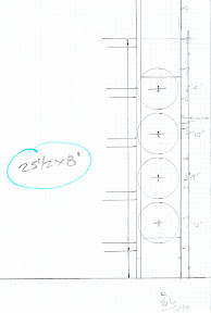
Why not use thd rod for the moveable SuperChunk design?
It could easily work, no flexing/warping ever.

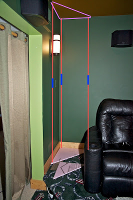
Pict is pretty self explain, bottom and top are piece of wood - thick mdf comes to mind.
You can make the 3 rods "invisible" by having then @ the corners and wrapped, or you go with an "industrial look" and have the 2 outside corner ones visible. I show a rod connector in blue, since I think normal Home Depot thd rods are not 9' long.....
[edit 2-18-2011; thd rod comes in 6' length max at Home Depot / Lowes]
I'm sure with little looking I could get my hands on some from a local supply house.


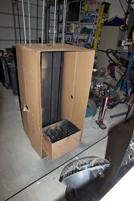
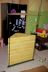
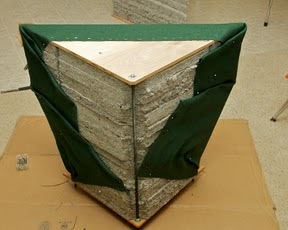
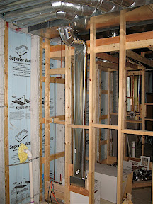
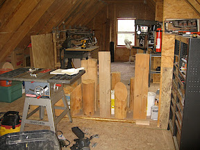
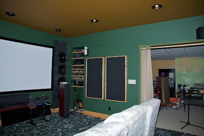
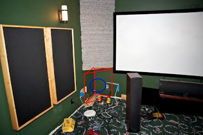
Here's what I've got so far on my rear broadband bass traps.

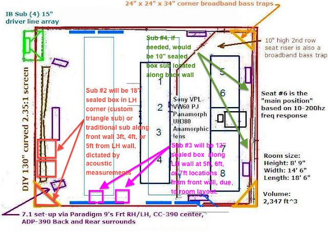
Each stack is (6) sheets of 2" thick 2' x 4' OC705 panels, cut 24" x 24" x 34".
The 24 triangles stack just over 48" high, I've decided to make them removable "corner tables".
The base board mldg will be removed and cut down after these done, so it will look integrated nicely.
fwiw: I have some more....Star Trek stuff to display, the 3D chess set, some ST:TOS replica phaser and tricorder, etc, collected over 20+ years.
So, the top will be nice wood, while the bottom possible mdf or even some leftover OSB I have. The 1/2 thd rod comes in 72" size.

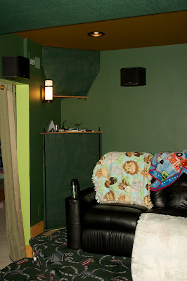
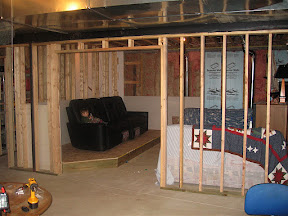
Now, above that display zone, which will get light w/o shadows via the sconces, will either be a 17" x 17" x 24" superchunk as shown on LH side, or a more visually pleasing triangular patch as shown on RH side, tbd.
Note: That Home Depot bag on the center table has (2) blue box AC gang boxes, I was going to move those sconces today fwd about 8" so I could have floor-ceiling "big" superchunks, but by putting a table top I've decided to not to do that.

(the boys and I watched a movie last night, sorry for the clutter)

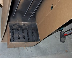
Regarding cutting the superchunks out of the 2' x 4' sheets, I started with the big bread knife, did 4, then tried the electric turkey knife.
My experience, the manual knife was MUCH easier to get dead straight and perpendicular lines cut, the electric knife seemed to walk on its own slightly, giving a wavy edge, not style points.


Here you can see what I'm talking about.
The bottom 4 were cut by hand/bread knife, the next 4 by electric knife.
It's not that much more time for hand/bread knife, 1st pass with edge guide sets the line, then 4 more passes holding the knife at a low 15-20 degrees gives perfect straight and perpendicular edge.
I suppose a jig could be made to ensure the electric knife is straight and perpendicular, but this manual method worked for me easily.


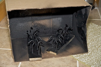
via makeshift paint/infra red warm booth I'm painting the thd rods......and the attach nuts/washers
.

2nd coat of paint on the thd rod and hardware in the garage

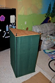
-final cut/paint the OSB base.
I added a 1 1/4 perimeter of 3/4 OSB so the thd rod/nuts won't be resting on the floor directly. Painted green, same as walls.


-Final cut/sand/stain the birch top board


These "Mikes Mondo Corner Bass traps", each will weigh 50+ lbs, looking back at my original plan of 1 huge removal bass trap.....nope that's 100+ lbs of weight, glad I went "1/2 size" then an additional trap in the top corners

they are huge, big, and sturdy
(YouTube video clip will show that)

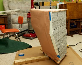
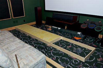
Layout the cut big triangles, cut back corner 3" x 3" 45 deg for clearance to rear thd rod


Stack 'em, trying to keep the leaning tower straight/aligned as it gets higher...


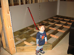
Me next to my the 4' stack, showing size of this beast.
However, mistake I made was NOT putting the rods in 1st before loading the triangles, so I had a PIA to get the rods in...lesson for #2
After fiddling here are the rods installed
.

I did NOT pre-cut the thd rod in the garage, had no way of knowing how much the OC705 would compress.
I actually can compress easily 1", more than 2", but the 1/2" birch ply top flexes too much at 2", I settled on 1" of compression, it felt very sturdy and solid.
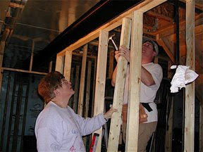
Green tape for cutting spot, my wife held the rod top while I used a Dewalt 18v buzzsaw.
Load in room, check for ingress/egress of loading the trap etc.
No other issues appeared to prep for fabric covering time
.

Cut the mid-hi freq blocker (kraft paper here) for the front face, install and hold with simple 1 3/4" craft pins


Cut the 56" wide fabric (roll size), for this first one I cut just 3/4" extra top/bottom (to 50", compress size is 48.5 "), it worked but for the 2nd one I increased that to 1" top/bottom extra for wrapping safety.
I should say this is a GLUE-LESS/PIN-LESS build for the fabric, I just use pins for the top to start, put the top birch ply board down and compress/tighten, keeping fabric not attached, and tuck the fabric in at the bottom.


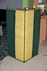
1st one "done", front face side
.

Backside looks good, needs covering


Now, the 2nd one went much quicker and smoother!
Make a 3 rod frame with base and top, gave 5" extra for loading.
This worked best for aligning the loose big triangles for flatness.


Kraft paper installed on 2nd bass trap:


Close-up showing 1" of extra material on the top before clamping down the birch ply.


2nd one done, and backside covered
.

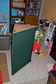
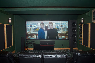
Loaded into the HT room, RH side one is the 2nd one made, it came out a little better.


YouTube video of them, http://youtu.be/lvBGTn4oXJI

Upper bass traps:
Plan A:
"smaller" triangles 17" x 17" x 24".
I was just going to build these, then I was wondering about what was the largest size I could build/fit up there?


Plan B:
I'll call this the "Trapezoid wedgie bass trap", consists of smaller triangles 17" x 17" x 24" blending into the biggie 24" x 24" x 34" to get more low freq absorption.
The thd rod will be hidden inside the bass trap except will show on the bottom.


I'm 90% going with Plan B, I think it will look nicer up there and the hidden rods is better for the upper location.
Unless I move those sconces full 24" x 24" x 34" size won't fit.

Additional 1/2" Birch plywood and thd rod/hardware bought yesterday.
This afternoon is build time.
I've got an idea on hidden holding system, will work on it a little more and if its doable will go with that.

btw, not all the Star Trek stuff will stay there, it will be de-cluttered, just showing my kids some of the stuff I had back in the day.
And YES, those Star Wars glasses are original Burger King glasses from the early 1980's, and those are genuine Apollo 13 glasses as well.
Unfortunately, Leonard Nimoy has not signed my "I am Not Spock" book...

2) "Trapezoid wedgie bass trap's" frames cut, stained, painted blk thd rod/hardware, assembled.
When you tighten the nuts up there is very little flex in this assembly, even prior to having the insulation in it.
There are other ways to make these obviously, but the thd rod IMO is easy, simple, and adjustable.

They are shown upside down here, that is how I'll cut/load them, starting from the big 24" x 24" x 34" triangles, and blending into the 17" x 17" x 24" as last one.
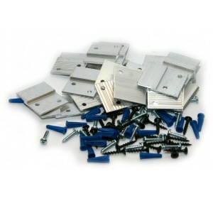
The 3/8-16 T-nut's worked perfect, nice and flush for ceiling mtg.


I'm needing more OC705 or the new stuff , ECOUSTIMAC Eco Friendly DIY Insulation.
I need (6) sheets of 2" 2' x 4' panels for these 2 bass traps, then I need (18) more sheets of same for my front wall bass traps...I'm, leaning towards the ECOUSTIMAC stuff.

1 done with material stacking, added loose pieces with sticky spray, worked great.


Putting on the Kraft paper to block mid-hi frequencies:
. .

1st one wrapped and done!
Those drywall edges made all the difference, I'm going to add those as lesson learned to lower bass trap post. Much crisper look.


.

Installing into the HT room.
I used a 30+ year old hydraulic bottle jack as 3rd hand...
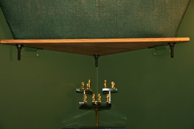
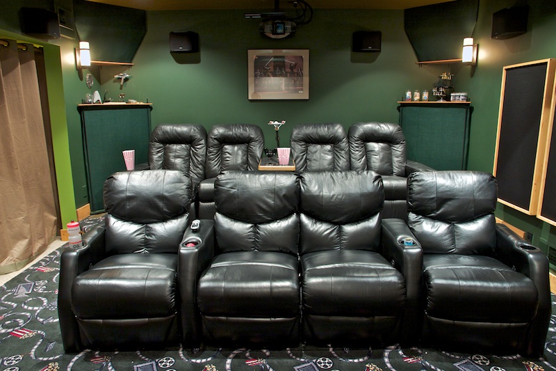

Both installed


Detail LH side....................................RH side
.

The upper bass traps are just sitting on (2) L brackets each, gotten from Lowes in the outside deck building area, painted them green.
By simple geometry they are trapped up there, not even attached screws to lower wood piece.
I did put 3/4" round felt on the top/ceiling piece to space it off the ceiling and ensure no vibrations.
Also on the wood edge to space it off the back/side walls, no issue with vibrations at all.
.

That completes the Rear wall broadband bass treatments.

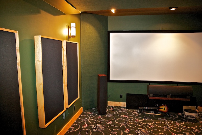
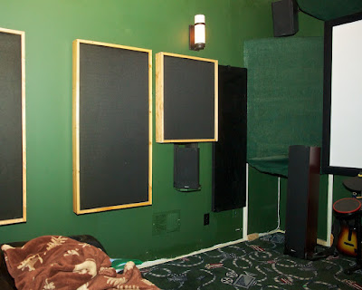
Now some front wall broadband bass treatments
A quick re-cap on my Front wall corner superchunk with "green" material, these were built 4/2011 thru 6/2011...slow but steady:

Cutting lots and lots of 24" x 24" x 34" triangles....nice to have non-itchy stuff.


Made a mid-support from 3/4" OSB to hold 2/3's of them 36" off the floor.
I did this as part of my front fabric mounting strategy as mid-support of the drywall corner edging and also just in case I ever wanted to tuck a sub there for whatever reason.
.

Top ones stacked


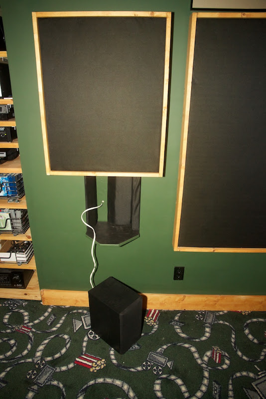
I realized the front wall speaker wires and side wall subwoofer coax needed to be moved....when building the HT I did not know about bass traps.
Cut and re-locate to 29" from the corner....use scrap wood as backer....tape/mud/paint....everything takes time.....


Instead of making a fabric frame, I used drywall corner edge and wrapped the fabric behind that.
Bend them from 90deg to 45deg by hand, went ok.
Also, used kraft paper to reflect mid/hi freq like my other bass traps, just cut and tuck tight.


The fabric was cut with 4" extra top/bottom, and 2.5" each side.
Initially I pinned the top for hanging, then tucked that under the ceiling.


Used plastic putty knife to tuck the sides.
I designed the drywall edge to be 1/8" off the wall, and then tucked the fabric behind that and the cut triangles.
A decent friction fit that stretched taught.

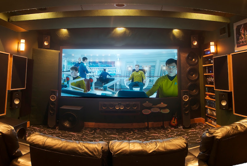
Done and absorbing some of those reflecting LFE!


This method was easy to do, an alternative to making the fabric frame and mounting that.

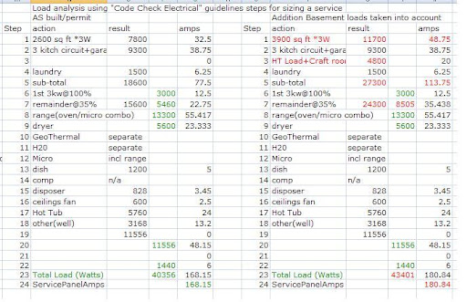
Picture is worth 1000 words.....
this simple pict should help visualize what I did above, excel can be useful for quick sketch...


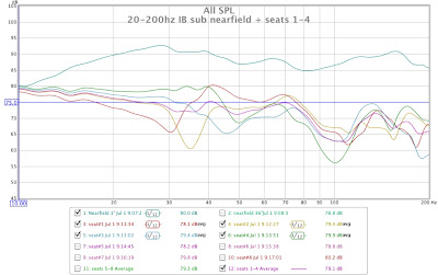
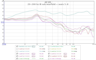
2nd row is almost deal flat across the LFE zone, 1st row not as good.

I also did freq listening of sub test tones with the RS db meter to grasp the chart to real life, a worthwhile thing to do, helps tie graphs to sound.

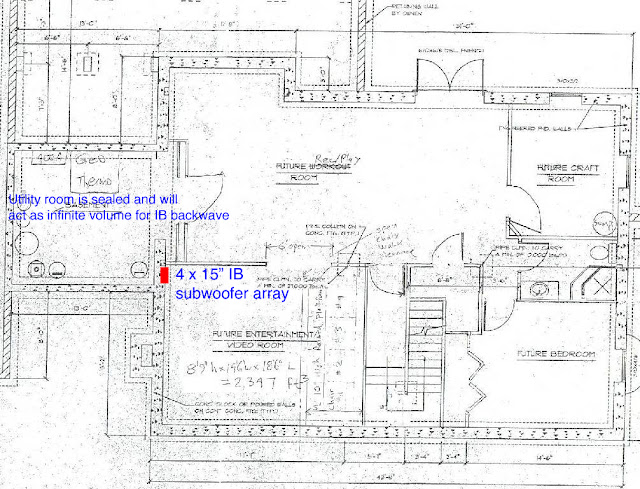
I had "leftovers" acoustic material from what I did earlier this year(2011), sitting in my utility room for months.
Wanted to improve the 1st row bass to be more consistent across seat-seat.

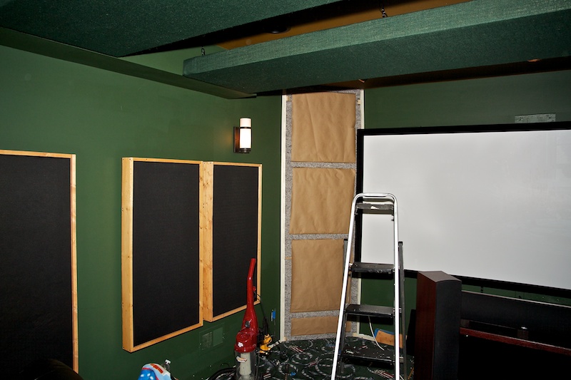
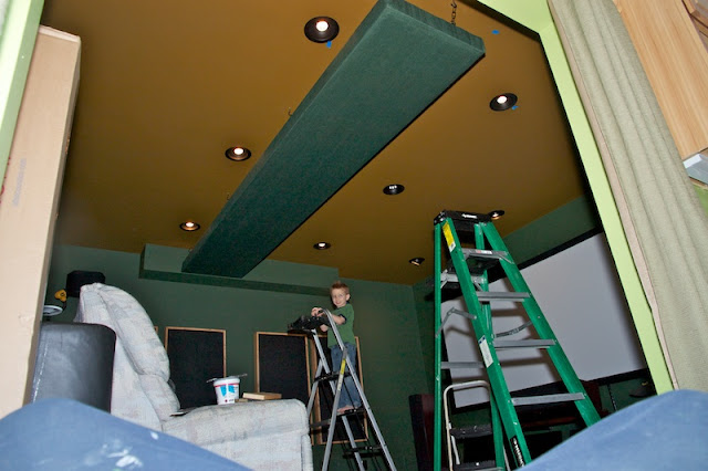
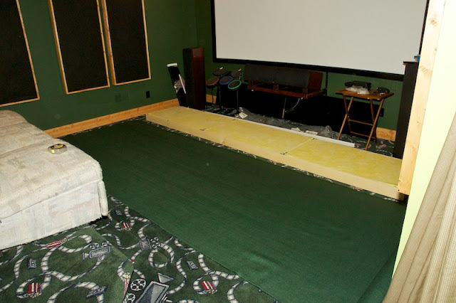
Yesterday (Saturday Dec-17-2011) I built a broadband bass trap that goes above my screen.
Basically 2' wide x 4' long panels that straddle the front wall/ceiling space.
I wanted a bigger trap, but due to the screen height and front lights this is as big as possible.
(LH side already has "big" superchunk style trap, 34" x 24" x 24", and RH side is IB subwoofer)

Construction method:
Bonded kraft paper to the front, and mounted them with just air gap for now.
I've got a roll of pink fluffy fiberglass that later I will put behind each one.
My plan is simply put a paper coated drywall corner edge on the top/ceiling edge, and then roll/fold the green burlap for a seemless look like I did the LH trap.

I realize not "by the book" of having the same gas flow resistivity porous material for a broadband bass trap, but since I had the materials lying around if some "free" improvements can be had why not.

Last edited by mtbdudexdad; 11-23-2013 at 05:56 PM.
  Reply With Quote
Old 11-23-2013, 12:22 PM   #7
mtbdudexdad mtbdudexdad is offline
Active Member
 
mtbdudexdad's Avatar
 
Nov 2013
Default

My basement HT had a 2008 Denon 4308CI in it and 7.1 set-up, worked fine, my family room had a 2000 Onkyo 787 5.1 set-up, the LFE sub pre-out went bad, so rather than replacing that directly.....I decided to upgrade the basement to the Denon 4520CI, and then upgrade the family room to the Denon 4308CI.....snuck that little face by the wife

So....getting an AVR with more capability....of course ya gotta use it!
That started me on the journey of going from 7.1 to 11.x in the basement HT.

After research, I decided on good bookshelf for my wides/heights, Paradigm Monitor.

For planning, here are 3 layouts for those considering 11.x
With Audyssey DSX and its competition Dolby Pro Logic IIz / DTS Neo:X™ in the market for a few years.
Audyssey visual:


This visual from my Denon 4520CI manual, makes it easier to grasp all the 7.1/9.1/11.1 speaker layout.


Here is the DTS Neo:X™ visual:


For Audyssey DSX, I asked Chris K what tolerances there are, because not everyone can do to the ideal layout, below is his answer.
Quote:
"Chris Kyriakakis"
Tolerance for Wides azimuth angle is ±10°. Elevation should be ear height.
For Heights we recommend: "slightly wider than the fronts and as high up as possible on the front wall".
I started with getting the wides sitting on bar stools with old college books to position them correctly.

On paper and using geometry guide looks correct for improved soundstage width.
However, since I have wide scope non AT screen (10 feet width, 130" diag) my mains are outside that already.

I've got the wides at correct 60 degree location. They do impeded into the theater space, less deep speakers are desired definitely.
When I re-do my side wall acoustic panels these speakers will be the 5" closer to the wall and acceptable.

Putting the heights up temporary was hard to do, due to acoustic broadband bass traps, so I had to tear those apart and put mtg brkt up.
I'm using 100' speaker 12/2 CL2 wire, task is routing the wire.
I'll tuck the wires inside the room length wise bass trap, that will work for height speakers.
Run it down the room height wise bass trap for LH wide speaker, take of the 3/4" thick pine base molding and router it's backside with a channel to hide the wire, then fish it behind the drywall up to the speaker.

Definitely best to do wiring at planning/build time, not after the fact.


I forgot how bulky my screen is, took it down with my 15 year old's help.
(Spanish foreign exchange student)


Ran the wires behind the upper bass trap and along the LH bass trap, meant taking all the triangles out and then back in again...
..

Got the heights mounted and the bass traps all modified/back, the wides wires routed and they are sitting on the bar stools still as temp solution, not sure on final method for them.


As for critical listening, lots of combinations going more than 7.1, that took lots of time.
..

Now, tackling the integrating of the wides into the walls, RH side, It's been 5 years since I saw these guts.. Determine studs, wires, etc. cut.
.

Ready for drywall, a pocket in the wall, it will be lined with acoustic absorption material.
Bottom will be pine shelf to support the bookshelf speaker, goal is speaker to be flush with the side acoustic panels.


My LH wall is outside foundation wall, it is engineered concrete with concrete studs that are 9 1/2" deep and 24" center, so I built a box to insert into the cavity as shown.
Leftover 3/4" thick OSB works nice, it takes drywall screws pretty good.
For the back I had 1/2" birch ply, so used that, since I did not have a 21" x 12" piece of OSB, wood scraps always come in handy.
Glue and screwed, box 100% sealed.
.

I had to contend with HVAC 8" dia pipe, so the box "wrapped" around that for maximum position ability - angle wise - of the speaker
Used pressure treated 2 x 4 for top/bottom support, as they contact the concrete studs, and then able to also screw into the RH side concrete stud, it is faced with 1" thick wood strip for drywall attaching.
Box is very sturdy in there.

Here is RH side, primed shows some spots I'll add more spackle and re-do, hey I'm not the best at mudding rolleyes.gif


Lesson learned:
Honestly, making the speaker box shelf outside of the wall and then "plugging it in" was much faster on the LH side than building it "in wall" as I did on the RH side, a small lesson learned.
With MLK day Jan 21st (next weekend is 3 day break) hopefully I'll have this done Tues Jan-22nd.

Speaker wire routing wise:
-LH side: I ended up for LH side going below the pine baseboard molding, then thru the bottom into the cavity the box is located and back out thru the back of the box.
-RH side: I was able to snake the speaker wire inside the staggered 2 x 4's wire "fishing wire" and my 6 year old skinny arm

Tucking the heights all the way up into the corner gives me 35 degree spread and around 32 degrees up.

The wides ended up at 50 degree spread, due to my desirte to keep symmetry of them.
The LH 8" HVAC pipe kept me from going more rearward on the LH side within the 24" span between concrete form studs, now if I went totally rear of that 8" pipe and the concrete stud then on the RH side I get into all my 4 circuits wiring for lights frown.gif
In the 2-3 year upgrade plan, if I do upgrade to a Grafiyik eye for light control then I'd need to re-do the box/wiring there, then I'd move these rearward and be around 62-63 degrees spread.

For now, I'm just within the +- 10 degree tolerance Chris K gave.
Layout:


Some pictures of final install:
.

This picture shows the dead flat varnish I coated the re-paint area....looks like I need to put a little more forward, they eyes can't see this or I would have of course done it.
I added that way back in 2008 to help the flat paint burnish issue.
.

I lined the sides/back/top of the box with 2" OC703 for resonance control, and to help my bookshelf breath, since it is rear ported.


added 2 subwoofers for flat freq response cliff notes
I'm joining the multi-sub approach, my IB sub does a great job but I can't get decent seat-seat flat respone in 1st row, the 2nd row is pretty decent seat-seat.
Based on by "Markus Mehlau" article here http://mehlau.net/audio/multisub_geddes/
Option 1:
Build a "helper" sub using Dayton Audio TIT400C-4 15" Titanic Mk III Subwoofer in 3.5 cu ft sealed box
(this has tight fit into the corner due to my screen and LH Main location......)
Option 1 has evolved into 2nd and 3rd sub approach, using an 18" driver for 2nd sub and 12" driver for 3rd sub
Here is graphic of that:


Option 2: (this discussion point)
Build a specific room designed Triangle sub w/ Dayton Audio RSS460HO-4 18" , amp, the sub triangle box will have 24" sides x 34" face x 32" tall; give or take 5.5 cu ft internal space after braces/etc.

Question:
If a triangle sub is possible and does not "break" the laws of boxed subs, then I'm doing option 2 and this thread can become a build thread, if not then I'll continue with option 1 and I'll get flat pack from Eric H @ DIY Sound Group.

Basic triangle sub image is this:


Located just as shown here ................. This will give symmetric balance to the IB 4 x 15" line array on the RH side:
.
You can see my corner bass trap triangle support, this triangle corner sub would be located just under that.

My main goal is the first row has modal issues that can't be solved via all the corner bass traps I've installed, so I'd like to smooth them more by installing a just as (almost?) capable sub on the LH side as my IB sub on RH side.
(I can't do a stereo IB sub on LH side or I would have)
It will be sticking out into the room, while the IB baffle plate on the RH side is about 4" into the room, not purely symmetric.....
1st row seats 1-4, you can see/hear the seat-seat variations..............................2nd row seats 5-8, very consistent across the seats::
.

after Much-much sub movements, sub in seat 1-4 positions (and taking so many measurements to guide decision making), then sub along both front wall and side wall, I decided to build 2 helper subs, one 18" SI driver in 4 cu ft sealed box, one 15" SI driver in 3 cu ft sealed box.

re-cap of that build for 1 sub:
3 cu ft flat pack build:
Dry fitting, Took me 10 minutes to un-pack and get my 3 cu ft sub box dry fit and tape together.:
.
Double top baffle plates removed to show nice fit inside
.

step 5a: Dry fit front baffle inner and outside piece, put 15" driver in place, use 3 thin items to position driver centered


step 5b: Pre-drill front baffles for 1/4-20 screws and thd fasteners, using box as a holding jig and the 15" driver holes as drill template - be careful when doing this, here you see some sawdust from drilling

Outside front

and the inner front all done same time and line up nicely


step 5c: carefully remove 15" driver - do this by pulling up outside front piece with one hand and then remove driver
step 5d: remove both outside and inner front baffles,
Lesson learned: Watch where your braces are...I had my screw holes lined up at 12/3/6/9 o'clock....and they each went into the brace end just slightly.
I had to open them up just a tad.


step 5e: drill 3/8 hole just 1/2 deep in the "inner" side of the inner front baffle, this is where the 1/4-20 thd fastener will go next step
I used these from Lowes, The Hillman Group 4-Count 1/4"-20 Zinc Plated Standard (SAE) Wood Insert Lock Nuts http://www.lowes.com/pd_148251-37672...ert&facetInfo=


step 5f: install thd fasteners into inner front piece, use 1/4-20 screws with washer to pull the thd fastener into the inner baffle from outside baffle side, put small amount of glue into each hole before doing this
>>This will ensure the 1/4-20 thd fasteners are perpendicular to the front baffle assy and also exact alignment to driver


All 8 done
.

step 6: glue along inner front piece & top/bottom/both sides contact, install inner front piece (a very slight tap needed), clamp, wipe off glue with slightly damp rag, let dry 2 hrs
.

step 7: apply glue to Outside front, temporary lay onto inner front and push down for glue contact both pieces
.

step 8: Remove Outside front, see where glue not contact, add glue and spread
(I was too busy here to take some picts....)

step 9: Final assy time! put Outside front back on, gently tighten the 8 1/4-20 screws as clamp for driver area, wipe glue with slightly damp rage off MDF the circle cutout
.

step 10: Apply 4 clamps to 4 corners approx 1" in both, wipe glue with slightly damp rage off MDF
.

.

step 11: add more clamps on outside and inside perimeter of front baffle, progressive tighten and wipe glue
.

sand the joints with palm sander, used 150 grit.
Just a few areas need slight touch up - barely, as I did not use brad nails.
I'll apply wood filler, let it dry, then sand with 220 grit.


Hit the edges with a wood file for slight 45 bevel:


Jasper Jig for 3 1/16" hole for the binding post cup


Done and fits perfect, pre-drill the 4 holes
.

I had $50 in Lowes gift cards, so went the quick/cheap route of Zinsser Bulls Eye Water Base Interior Primer had them tint it grey, then flat black Valspar Ultra , the Lowe's paint guy said its a very durable paint, from the spec sheet
Quote:
Thick, 1 coat coverage. Stain-resistant and scrubbable
I'm painting primer Baffle face down first, then after drying overnite I'll flip onto rear and paint the baffle front tomorrow. Then same for the flat black final coat.


Paint 2nd coat after 2-ish hours, then flip dried painted surface onto these 2 x 4's covered with old rag to make sure new paint not stick to the raw wood, worked fine:


Keeping paint fresh for 12-18 hrs via food wrap, leave little air as possible


I applied 2nd coat onto the front baffle and 3rd coat onto the sides


flip back over, and start with the flat black.
Even with the gray primer I can see not 100% coverage, definitely a 2nd coat needed.


Here the box is all painted, I put a photo gray card to calibrate correct greysacle and see how "black" the flat black is to reference black.....nice to say black is black.
.

now just need to solder wires to the binding post cup, mount that, stuff polyfill, wire & mount the driver, then .... box #1 done, built 2nd one very similar.

You can see the 2 added subs against the front wall and LH side wall


reserved for lessons learned and thoughts
(and this is my last "reserve" post )

Last edited by mtbdudexdad; 11-25-2013 at 04:37 PM.
  Reply With Quote
Old 11-23-2013, 12:23 PM   #8
Almadacr Almadacr is offline
Blu-ray Ninja
 
Almadacr's Avatar
 
Mar 2011
1
57
527
4
10
Default

welcome to the galleries you have a kick ass room .
  Reply With Quote
Old 11-23-2013, 12:25 PM   #9
hometheatergeek hometheatergeek is offline
Blu-ray Grand Duke
 
hometheatergeek's Avatar
 
Feb 2008
Near Atlanta GA
48
39
290
40
2
Default

Hello and welcome to the galleries mtbdudexdad. I saw some of your other postings and was waiting for you to get your thread going. It is a wonderful room you have designed and setup. I really like the quad IB 15" sub array. You must get some really cool ULF in that room. Have you ever watch Dredd and seen/heard/felt the classroom scene?
  Reply With Quote
Old 11-23-2013, 12:38 PM   #10
Johan1981 Johan1981 is offline
Active Member
 
Johan1981's Avatar
 
Sep 2008
19
15
1
Default

Welcome to the gallery forum! As I previously stated, very nice HT!
  Reply With Quote
Old 11-23-2013, 01:10 PM   #11
mtbdudexdad mtbdudexdad is offline
Active Member
 
mtbdudexdad's Avatar
 
Nov 2013
Default

Thx Almadacr, hometheatergeek, johan81, and others...
what I'll try and convey here is.
-by DIY and sweat equity it is possible to have a decent HT
-be patient, and don't use credit cards if possible, the "pay as you install" plan takes longer, but it's easier to sleep at night knowing you do not "owe the man"
-have fun, learn, be humble and ask for help
-share and give back to the community by helping others
-I do believe in both subjective and objective, as a Professional Engineer data is the basis for the scientific method
  Reply With Quote
Old 11-23-2013, 01:27 PM   #12
darkpoet25 darkpoet25 is offline
Blu-ray Samurai
 
darkpoet25's Avatar
 
Feb 2007
Indianapolis, IN
45
50
297
4
Default

I bet that set up sounds amazing. Incredible job you've done there. What other equipment are you using to get the 11.3?
  Reply With Quote
Old 11-23-2013, 01:42 PM   #13
Billy13 Billy13 is offline
Blu-ray Count
 
Billy13's Avatar
 
Mar 2013
Somewhere Between Heaven ↑ & Hell ↓ ......
436
115
63
Default

That's really quite an impressive HT you have built

I love log cabins, very nice place you have
  Reply With Quote
Old 11-23-2013, 02:45 PM   #14
Revolver517 Revolver517 is offline
Blu-ray Ninja
 
Revolver517's Avatar
 
Jan 2013
Michigan
66
574
84
Thumbs up

Wow what an amazing HT and home you have. You put in a lot of time and effort into building your dream theater. Now you can sit back and enjoy all your hard work.
  Reply With Quote
Old 11-23-2013, 09:31 PM   #15
mtbdudexdad mtbdudexdad is offline
Active Member
 
mtbdudexdad's Avatar
 
Nov 2013
Default

Quote:
Originally Posted by hometheatergeek View Post
Hello and welcome to the galleries mtbdudexdad. I saw some of your other postings and was waiting for you to get your thread going. It is a wonderful room you have designed and setup. I really like the quad IB 15" sub array. You must get some really cool ULF in that room. Have you ever watch Dredd and seen/heard/felt the classroom scene?
The LFE exceeded my expectations.
Here are the 34 seconds of the final fight scene in K-F-P, where Panda is fighting Tiger. 126db @ last part, the famous wa-tu-shi finger hold scene!!
http://youtu.be/Lq5oDn7m4wQ


Yes of course, Dredd in 11.3 discrete, as it's 1 of 3 titles released in DTS-MA 7.1 and Neo:X


Quote:
Originally Posted by darkpoet25 View Post
I bet that set up sounds amazing. Incredible job you've done there. What other equipment are you using to get the 11.3?
The trigger for going to 11.x was my family room 2000 Onkyo-787 sorta died, so I put the Denon 4308CI up there and bought the Denon 4520CI for the HT.
With that, it has 11.2 ability, with 9 internal amps, so needed the Emotiva XPA-3 for the front soundstage. Added the Paradigm bookshelf Monitor's for wides/heights.

Quote:
Originally Posted by Billy13 View Post
That's really quite an impressive HT you have built

I love log cabins, very nice place you have
Thx, it's been a evolving journey, with many things learned, mistakes made, etc.
Plus, with a log home I get good excuse to rent one of these 50ft boom cranes every 5 years for exterior re-staining...
I've got a 36' ladder, but I do feel more comfortable with the big boom crane 3 stories up.


Quote:
Originally Posted by Revolver517 View Post
Wow what an amazing HT and home you have. You put in a lot of time and effort into building your dream theater. Now you can sit back and enjoy all your hard work.
We know better than that, enjoy for a while, then plan for the next "big thing/upgrade".....
4k pj in 2015 or 2016??
Dolby Atmos in .... 2017? "Voice of God" speakers, true discrete arrays.....

Last edited by mtbdudexdad; 11-23-2013 at 09:56 PM.
  Reply With Quote
Old 11-25-2013, 09:59 PM   #16
hyghwayman hyghwayman is offline
Active Member
 
hyghwayman's Avatar
 
Jun 2013
Earth for Now
22
24
3
Default

WOW ,
thank you for sharing what you have learned throughout your build.
  Reply With Quote
Old 11-26-2013, 03:22 AM   #17
mtbdudexdad mtbdudexdad is offline
Active Member
 
mtbdudexdad's Avatar
 
Nov 2013
Default

Quote:
Originally Posted by hyghwayman View Post
WOW ,
thank you for sharing what you have learned throughout your build.
Thank you.
Standing on the shoulders of many people, read lots of books, looked at many forums, lots of few hours sleep
(remember Sound & Vision? I was active there 2007-2009 before it went totally south and they closed it)

Hopefully others can get the DIY mentality, save $$ by sweat equity, put that saved $$ into the HT (so I tell my wife )
  Reply With Quote
Old 11-29-2013, 06:01 PM   #18
mtbdudexdad mtbdudexdad is offline
Active Member
 
mtbdudexdad's Avatar
 
Nov 2013
Default

Summary of my HT project costs - to date 11/2013

Front Proj: 2008 Sony VPL-VW60 $4k then;
Panamorph a-lens 2008 UH380 on slide $2.2k
2013 Darblet video processor; $300,
A/V: 2012 Denon AVR-4520CI ; approx $2.2k
Emotiva XPA-3 amp; $600 - I have 11.3 set-up so needed this as no AVR currently has 11 amps, mine has 9
Screen: 130" DIY 2.35:1 curved screen; $600-ish, if you buy $1.5k or so
11.3 speakers: Paradigm Monitor 9's for front, CC-390 center, 4 ADP-390 for rear and back surround, Monitor bookshelf for wides/fronts.; I have about $4k in these, maybe slightly more.

subwoofer: 4 x 15" IB array on Sub1, plus 18" and 15" Stereo Integrity cubes on Sub2; My IB sub $1.3k, the 2 added cube subs $800, total $2.1k
>> DIY soundgroup has sub cubes, or better yet now Parts Express is carrying them with drivers bundled to save $$
speaker wire: 500 feet of 14ga/4c, all runs equal length.; $250? (copper prices change too fast)
Seats: 2 rows thru Roman $2.5k
DIY Acoustics: $1.3k

My gear + acoustics + seats total comes to $23k-ish, then add in carpet + pad ($2k top tier), drywall/soundproofing/etc ($2k), AV rack ($500), remotes ($500), $500 12ga/14ga wiring, lighting $500 (fixtures & what not, also add $750 if grafik eye), misc stuff $1k (riser, a-lens slide, etc) .

So approx $30k spread over 6 years.

What have I learned? (not in priority order, rather as I typed them)
1) A lot about acoustics, as the first 2 years of my HT was with bare drywall
2) It's so easy to get onto the "upgrade-itis" bandwagon, resist as long as you can, technology improves and costs come down, always
3) If you went with the 1/3 parts/materials + 2/3 labor/mark-up rule of building, then possible the HT could have costed $100k. That seems way high, however I can see here around $20k or so labor that I "offset" by DIY.
4) Acoustic treatments can be effectively added after the fact, however soundproofing truly needs upfront planning, design, and construction methods grasped correctly for effectiveness
5) HVAC; this is best tackled when building your home newly, to already plan on a multi-zone system, then add your HT space to that is easy. 8 people in closed door HT generates more BTU's than most people realize
6) Electrical; I totally read books, studied code. Did analysis on existing 2 200amp panels, decided new circuits should go where, did load analysis, did layout with proper symbols. Did all the elect myself.
7) Plumbing; learned how to sweat a proper joint, got pretty good at routing. Since then I've helped my family and inlaws install 4 water heaters, 1 new well pressure tank.
8) General framing and drywall prep. Learned framing techniques, tips. Also, learned how to think like a drywall person, where backers need to go for proper drywall attaching.
9) multi-sub route is nearly mandatory for those with more than 1 MLP and desire "good" LFE across multiple seats/rows. Unless you want to really learn and apply membrane absorbers.

Last edited by mtbdudexdad; 11-30-2013 at 12:32 AM. Reason: added info
  Reply With Quote
Old 11-29-2013, 06:16 PM   #19
Badas Badas is offline
Blu-ray Knight
 
Badas's Avatar
 
Aug 2008
LOTR Auckland, New Zealand (Down Under)
139
102
1412
16
11
10
Default

The most amazing build I have seen on this site. Thanks for all the detail. Beautiful room and home. Well done.
  Reply With Quote
Old 11-29-2013, 06:19 PM   #20
Billy13 Billy13 is offline
Blu-ray Count
 
Billy13's Avatar
 
Mar 2013
Somewhere Between Heaven ↑ & Hell ↓ ......
436
115
63
Default

Quote:
Originally Posted by Badas View Post
The most amazing build I have seen on this site. Thanks for all the detail. Beautiful room and home. Well done.
Plus1

I love what you did with the subwoofers I'm guessing your audio/video experiences are like you're on
  Reply With Quote
Reply
Go Back   Blu-ray Forum > Home Theater > Home Theater Galleries


Posting Rules
You may not post new threads
You may not post replies
You may not post attachments
You may not edit your posts

BB code is On
Smilies are On
[IMG] code is On
HTML code is Off

Forum Jump


All times are GMT. The time now is 07:32 PM.